Producibility Index
Producibility Index module is used to detect and highlight small holes and gaps in the geometry that are difficult to manufacture in AM Process. The tool can highlight critical thin wall features in the geometry that may be fused during the laser sintering process and depends on laser diameter or nozzle diameter.
Instructions
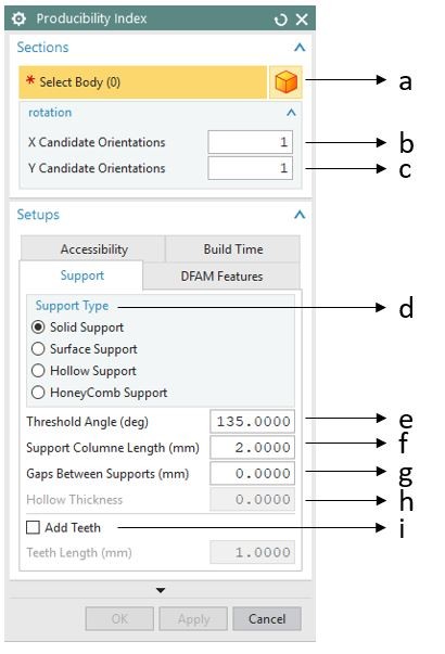
Figure 1 Producibility Index GUI Support
The Producibility Index GUI is shown in the figure below. The detailed explanation of each option in the GUI is given below.
a) Select Body
This option is used to select the body for which thin walls are detected and highlighted.
b) X Candidate Orientations
Number of rotation angle in X direction. (e.g. input as ‘3’, 00 ,1200 ,2400 will be checked)
c) Y Candidate Orientations
Number of rotation angle in Y direction. (e.g. input as ‘3’, 00 ,1200 ,2400 will be checked)
d) Support Type
Solid Support: Each support column generated will be solid.
Hollow Support: Each support column is hollow (thickness can be entered in option
Surface Support: Support columns are surfaces with no thickness. The minimum thickness for support structures will be the laser diameter used to sinter the material powder using DMLS.
Honeycomb Support: This type of support structures columns is connected with each other. During post-processing operations for support structure removal interconnected support structures are less prone to chip off and damage critical features of the part.
e) Threshold Angle
The angle between the part surface normal and the build direction (Z axis) is entered here. The default value is set to 135 degrees.
f) Support Column Length
Support Column length is the center-to-center distance between two adjacent support columns (square cross-section). It is also the side length of the cross section of the support column (square cross-section). Values ranging from 1.00 to 4.00 are optimal. A lower value will take longer computational time due to more number of support structures. A higher value of overhang length will generate fewer support structures making the solution sub-optimal.
g) Gap Between Supports
This is the side-to-side gap between two adjacent support columns. The Gap Between Supports should always be less than the Support Column Length
h) Hollow Thickness
This value provides thickness to hollow support structures.
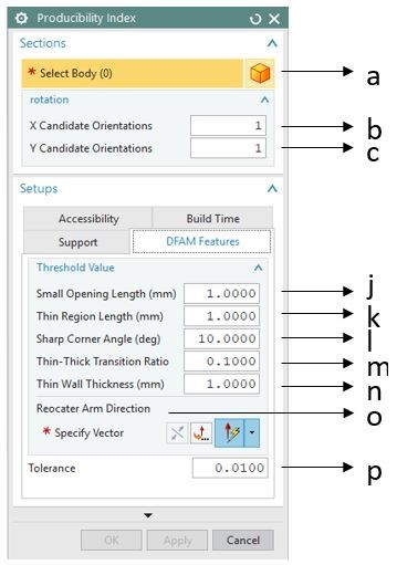
Figure 2 Producibility Index GUI DFAM
i) Add Teeth
Check this box if you want to create support structures with a tooth at the support to part contact region. Removal of support structures with teeth is easy and will not damage the parts during post-processing. The contact area of support structures will be less if this option is selected. Teeth length is the side dimension of the top side of the teeth (as shaded by red in the figure). A value of zero teeth length means the support contact region is a point. Thus, the support contact area calculated will be 0 mm^2.
j) Small Opening Length
The threshold length of the gap that is identified as a small opening is entered here. (unit in mm).
k) Thin Region Length
Threshold thickness of the region that is identified as thin region is entered here. (unit in mm).
l) Sharp Corner Angle
The threshold angle of the corner that is identified as a sharp corner is entered here. (unit in degree)
m) Thin-Thick Transition Ratio
The threshold ration between area of two continuous slice contour that is identified as a thin-thick transition is entered here.
n) Thin Wall Thickness
The threshold thickness of wall feature that is identified as a thin wall is entered here. (unit in mm).
o) Recoater Arm Direction
The moving direction of the recoater arm.
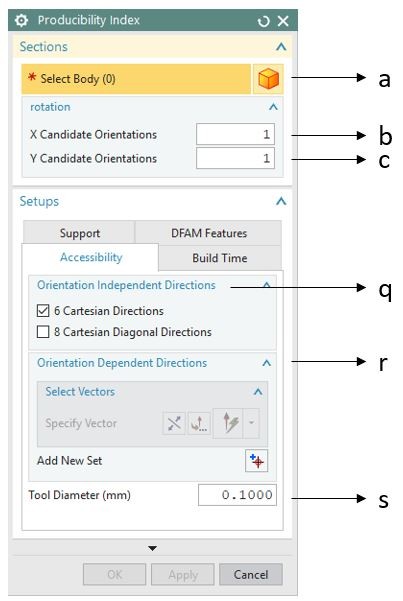
Figure 3 Producibility Index GUI Accessibility
p) Tolerance
The tolerance for checking whether two neighbor lines are considered as one line. Keep default value for most cases.
q) Orientation Independent Directions
the fixed tool approaching directions.
6 Cartesian Directions: the direction following the +X, -X, +Y, -Y, +Z, -Z.
8 Cartesian Diagonal Directions: the direction following the isometric direction in the 8 octants of the Cartesian coordinate system
r) Orientation Dependent Directions
Add user specified direction as approaching direction for accessibility check
s) Tool Diameter
The diameter of the cutting tool for the support, all points lying inside the cylinder defined by the approaching direction and tool diameter must be accessible
t) Laser Diameter
The diameter of the laser spot
u) Laser Speed
The traveling speed of the laser spot
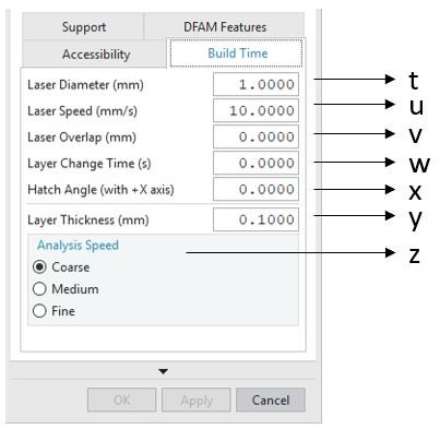
Figure 4 Producibility Index GUI Build Time
v) Laser overlap
The overlap width of two parallel laser travelling path
w) Layer Change Time
The time for recoating the building chamber
x) Hatch Angle
The angle of the hatch pattern respect to the X axis
y) Layer Thickness
The thickness of layer during the building process
z) Analysis Speed
Adjust the slice thickness during the analysis, “Coarse” means larger slice thickness and faster, “Fine” means small slice thickness and slower
The output window of the Producibility Index is shown below.
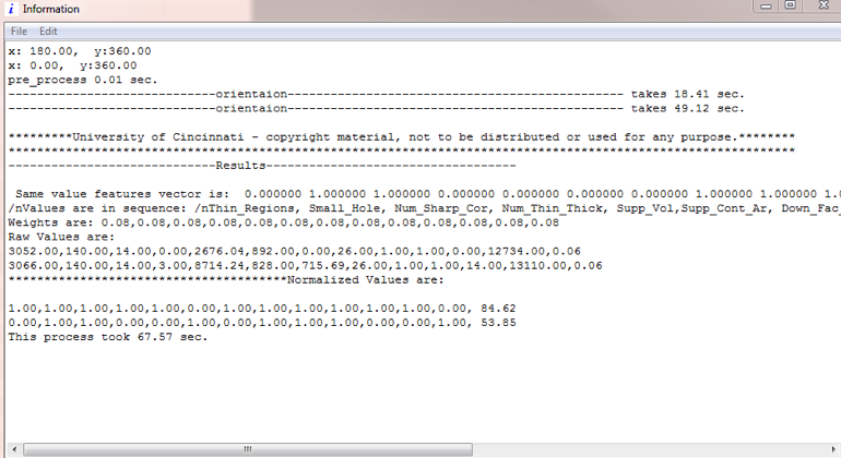
Figure 5 Producibility Index Output Window
Please watch the video tutorial of the module for an example part included with the zip file of the module.
Example Problem
Use the Parasolid File named Producibility_Index.x_t in the Example Parts folder attached in the Producibility Index module folder that you have extracted from the website.
Open the example part, try the following input configurations and note the changes of the thin walls.
a. Select the part, set the X Candidate Orientations as “2”, the Recoater Arm Direction as “YC”, keep all other parameters as default, click “OK”, check the results.
Download Producibility Index Tool