Transmission Loss of an Expansion Chamber Example
Purpose
The purpose of this example is to introduce students to the interface of NX Nastran (or Simcenter 3D) and how to model and solve vibro-acoustic problems.
Learning Outcome
Student can learn how to describe interactions between structures and acoustic medium and how to model structural-acoustic coupling problems by using NX Nastran.
Introduction to the problem
An expansion chamber (muffler) is a simple example in acoustics. The expansion chamber is used to attenuate noises. By using harmonic analysis in NX Nastran, sound pressure in the chamber can be calculated. Based on the sound pressure at the inlet and outlet of the chamber, transmission loss of the chamber can be calculated to investigate the performance of the chamber. In addition, the muffler structure and acoustic cavity interact with each other, therefore the muffler is not effective to reduce noise level at the natural frequencies of both the muffler structure and acoustic cavity.
Steps
- Create FEM File
- Load Geometry
- Geometry Preparation
- Create Microphones
- Create Mesh
- Assign Materials
- Create SIM file
- Solution setup
- Boundary Condition
- Solve FEM Model
- Post Processing
Create FEM File

Figure 1
Click “New” to create simulation from the upper menu bar as shown Figure 1.

Figure 2
Check “NX Nastran Vibro-Acoustic, Type: Fem” and set file name and folder as shown in Figure 2.
Load Geometry

Figure 3
As shown in Figure 3, load CAD file (muffler.prt).
Geometry Preparation

Figure 4
From the Simulation File View, right-click and left-click “Make Displayed Part, and then click “Promote” from the Start menu as shown in Figure 4.

Figure 5
Now, select a whole geometry of the muffler structure as shown in Figure 5, and then click “OK”.

Figure 6
Click “Midsurface by Face Pairs” from the “Geometry Preparation” tab as shown in Figure 6.

Figure 7
And then, as shown in Figure 7, set the properties of “Midsurface by Face Pairs” tab to create shell structure from the solid model of the muffle.

Figure 8
Now, you can see the mid-surfaces created that appear in model tree as shown in Figure 8.

Figure 9
In order to create acoustic medium, we have to remove holes from the structure, which are an inlet and outlet of the muffler. Click Geometry Preparation → More → Bounded Plane as shown in Figure 9.

Figure 10
Click the curve of the inlet as shown in Figure 10, and click apply. We can see that the inlet is closed by surface. Repeat this for the outlet.

Figure 11
After removing all holes from the structure, we can create a volume of acoustic medium by using “Surface Wrap Recipe”. First, deactivate polygon body (3D) as shown in Figure 11.

Figure 12
Then, click Surface Wrap, Surface Wrap Recipe as shown in Figure 12.

Figure 13
From the property window of the Surface Wrap Recipe, select all polygon geometry (2D), set Global Resolution as 5 mm, set type of Surface Wrap Interior/Exterior as “Interior Point”, and then select any point inside of the muffler as shown in Figure 13.

Figure 14
From the model tree, click Surface Wrap Recipes, Surface_Wrap_Recipe1, Wrap as shown in Figure 14.

Figure 15
From the model tree, activate only Surface Wrap Body (Figure 15).

Figure 16
You can see the volume of the acoustic medium (Figure 16).
Create Microphones

Figure 17
Click Nodes and Elements, Elements, More, Point Set as shown in Figure 17. Point Set Mech Primitives window is opened and add 3 microphones as shown in Figure 18.
Further action is required to make this image accessible
One of the below criteria must be satisfied:
- Add image alt tag OR
- Mark image as decorative
The image will not display on the live site until the issue above is resolved.
Further action is required to make this image accessible
One of the below criteria must be satisfied:
- Add image alt tag OR
- Mark image as decorative
The image will not display on the live site until the issue above is resolved.

Figure 18
And then we can see 3 microphones inside of the muffler as shown in Figure 19.

Figure 19
Create Mesh

Figure 20
To create mesh of the acoustic medium, click “3D Tetrahedral” (Figure 20).
As shown in Figure 21, select the volume of the acoustic medium, and set the properties.

Figure 21

Figure 22
Now we can see the mesh created for acoustic medium shown in Figure 22.
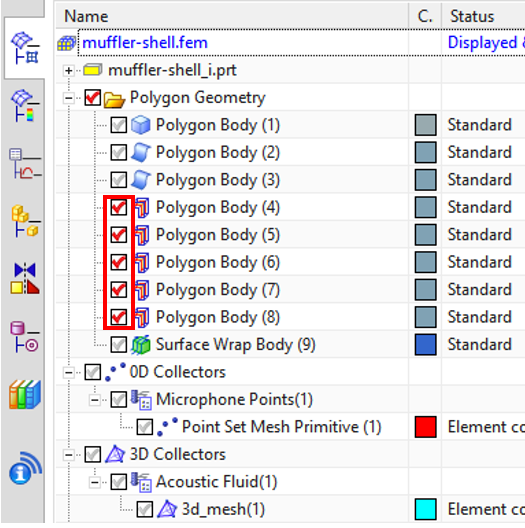
Figure 23
Now, we will create 2D mesh for the muffler structure. First, from the model tree, activate only muffler structures (2D) and exclude surfaces of holes as shown in Figure 23.
Click “2D Mesh” from the Mesh tab as shown in Figure 24.

Figure 24
From the property window, set the properties for 2D mesh as shown in Figure 25 and click OK.

Figure 25

Figure 26
We can 2D mesh for muffler structure as shown in Figure 26.
Assign Materials
From the model tree, right-click Acoustic Fluid (1) and click Edit. As shown in Figure 27, set the parameters as shown below:
Mesh Collector
- Type: PSOLID – Acoustic Fluid
- Acoustic Fluid Property: Click Option
PSOLD – Acoustic Fluid
- Name: Set name of the material
- Properties: Click “Create Material”
Material List
- Click “Create Material”
Fluid Material
- Density (RHO): 1.225 kg/m3
- Speed of Sound (C): 340 m/s

Figure 27
Similarly, set the material of the muffler structure as aluminum as shown in Figure 28.

Figure 28
Create SIM File
From the model tree, right-click on fem and select “New Simulation”. And then, select “NX Nastran Vibro-Acoustics, Type: Sim” and set file name and folder as shown in Figure 29.

Figure 29
Solution Setup
When Solution window is open, click Edit on Vibro-Acoustic Output Request 1 as shown in Figure 30.

Figure 30

And then, set the parameters as shown below and Figure 31.
- Sorting: SORT2
- Entity: Group
- Node Selection: MIC points

From the Bulk Data in the Solution menu, click Fluid-Structure Interface Modeling Parameters, Create Modeling Object as shown in Figure 32. This enables coupling between acoustic medium and muffler structure. And then, set the Type of Coupling as Two-Way Coupling as shown in Figure 33.

Figure 33
Set output request and forcing frequencies as shown in Figure 34. Out frequency range of interest is 2- 2000 Hz with 2 Hz frequency step.
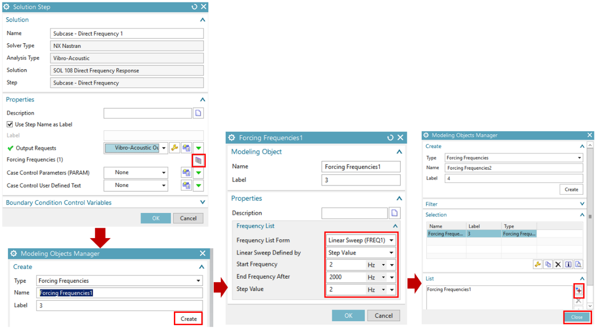
Figure 34
Boundary Condition

Figure 35
We have two boundary conditions to be applied at the inlet and outlet of the muffler. First, we need to apply anechoic termination at the outlet, which means there is no reflection. Such a boundary condition can be applied in NX Nastran by using Automatically Matched Layer. Click Loads and Conditions, Simulation Objective Type, Automatically Matched Layer as shown in Figure 35.

Figure 36
Click “Create Region” in the Automatically Matched Layer Property window as shown in Figure 36.
And then, click “Select Object” and click the outlet of the muffler as shown in Figure 37.

Figure 37

Figure 38
Now, we will apply acoustic pressure at the inlet of the muffler. Click Loads and Conditions, Load Type, Enforced Acoustic Pressure as shown in Figure 38.
And then, click “Select Object” and click the outlet of the muffler and set the magnitude as 1 as shown in Figure 39.

Figure 39

Figure 40
In addition, the inlet and outlet edges of the muffler will be fixed. Click Loads and Conditions, Constraint Type, Fixed Constraint as shown in Figure 40.
And then, click “Select Object” and click the edges of inlet and outlet of the muffler and as shown in Figure 41.

Figure 41
Solve FEM Model
Click “Solve” to start calculation as shown in Figure 42. In addition, we can set the number of cores for parallel processing from “Edit Solver Parameters.”

Figure 42
Postprocessing

Figure 43
Once solution is complete, we have to do postprocessing to calculate transmission loss of the muffler. NX Nastran provide an option to calculate transmission loss by using “Post-Processing Scenario.” Click Solution 1, Results, Vibro Acoustic, Post-Processing Scenario as shown in Figure 43.
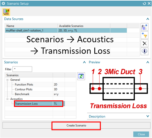
Figure 44
When the Scenario Setup menu is open, click Scenarios, Acoustics, Transmission Loss, and then click “Create Scenario” as shown in Figure 44.

Figure 45
Now, we have to select microphones at the inlet and outlet. Select “Inlet Nodes” as 1 and 2, “Outlet Node” as 3, and Surface Area Ratio Inlet/Outlet as 1 as shown in Figure 45.
Now we can see the transmission of the muffler as shown in Figure 46.

Figure 46