Design and analysis of Bezier surfaces
Bezier surface is generated by a set of control points in u, w directions. Usually a Bi-cubic Bezier surface is generated with a set of 16 control points. It is challenging for students to understand the changes in Bezier surface as the change in control points. This is a GUI which simulates the behavior of this Bi-cubic bezier surface using NX API, C++ and Ufuncs. This enables students to interact with GUI by providing various control points and visualize their effect on the shape of surface. This tool assists students with their assignment in visualizing and validating their work.
Installation Manual
- Download and extract the contents of the .zip file named Design & Analysis of Bezier Surfaces.zip.
- Open the extracted folder named Design & Analysis of Bezier Surfaces.
- Open the folder named ug_customization. Right click on the Windows Batch File named nx and open with Notepad/Notepad++.
- Find the current file path of the nx file in your computer (Right click >> Properties). Copy the file path and paste it in the first line (the highlighted portion in the notepad as shown below).
- Change the version of Siemens NX to the one you are using (module works for Siemens NX 10.0, 11.0, and 12.0) in the third line of the notepad file (as highlighted below)
- Once these steps are carried out, you have completed the installation procedures before launching the application.


Instruction Manual
- Now, double-click nx to launch the Windows Batch File. This will launch the Siemens NX window and a terminal window (you can minimize it or close it – it contains the information you input in steps 4 and 5). You may notice the UC Geometric Modeling Modules tab in the top toolbar. Click on it. The Design & Analysis of Bezier Surfaces module will be visible.
- To create a Bi-cubic bezier surface the user is supposed to specify all the 16 control points. For illustration purposes, the text files with bezier surface control points are saved in the folder named Examples.
- Once the Siemens NX is launched, you can click on the Design & Analysis of Bezier Surfaces button on the Command Ribbon.
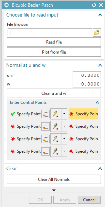
- The Design & Analysis of Bezier Surfaces GUI is shown in the figure below. The detailed explanation of each option in the GUI is given below.

NX API based GUI
a) File Browser
Browse the text file with the control points of the Bi-cubic Bezier surface to be generated.
b) Read file
Used only when getting the surface control points from a file. Reads the control points of the Bezier surface and plots them on the NX window.
c) Plot from file
Generates the Bezier surface with the control points from the file.
d) Clear u and w
Clears the plotted normal at the specified u, w on the generated bezier surface.
e) Enter Control Points
To manually specify all the control points of the bi-cubic bezier surface use either the point dialog of specify point or the cursor on the NX window. and then use ‘Apply’ or ‘Ok’ to generate the surface.
f) Clear All Normals
Clears all the normal generated on the surface.
If the changes made are to be saved use ‘OK’ or ‘Apply’, else use ‘cancel’. To undo the plot of the Bezier surface use ‘ctlr+Z’.

Bi-cubic bezier surface with normal all over the surface
5. The output window of the Design & Analysis of Bezier Surfaces module is shown below. The result consists of the bezier surface, normal at the specified u, w and normal all over the surface.

Output from the GUI
Please watch the video tutorial of the module for an example included with the zip file of the module.
Example Problem
Generate the bezier surface with all the four different sets of control points provided with the module and visualize the impact of change in control points on the shape of Bi-cubic bezier surface.
Download Design & Analysis of Bezier Surfaces